Lithium Polymer batteries have a lot of advantages compared to the standard rechargeable NiMh or NiCd batteries.
It is mainly the weight per cell and per Wh. A LiPo battery can also be much more smaller by having the same capacity and voltage (compared to a NiMh or NiCd rechargeable battery).
This makes the LiPo very useful for small embedded systems, computers (notebook or tablet PCs), phones (smart phones) , etc., (or everywhere else a low weight is needed e.g. RC Hobby…).
Using a LiPo is not as easy as using NiMh batteries. Charging and discharging a NiMh battery (or battery pack) is easy. Discharge until the application stops working, change the battery and meanwhile charge the other one. A charged NiMh cell has a voltage about 1.2 V a discharged one about 0 V (or everything between 0 and 1.2 V).
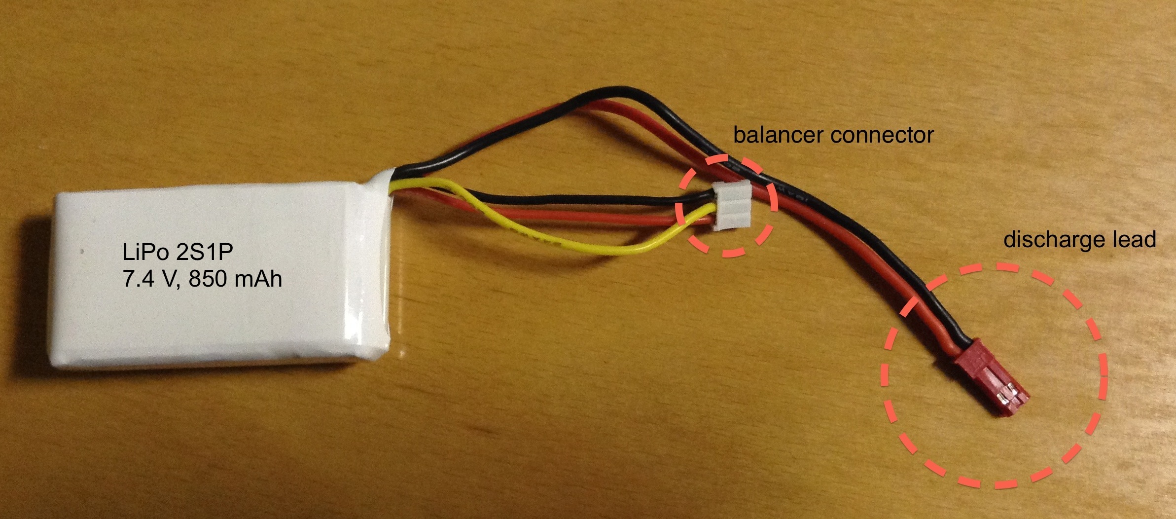
A LiPo cell has a voltage about 3.7 V when it is discharged and a voltage about 4.2 V when it is fully charged. Here comes the first problem: Discharging a LiPo cell should not go under 3.5 V (this value is controversially discussed) but it is easy to damage a LiPo cell by discharging it below 3 V.
This is the reason why every application which is using a LiPo battery (or battery pack) needs a monitor. The monitor takes care for the battery. The easiest way to monitor such a battery is to check the cell voltage.
IF CELL_VOLTAGE < 3.5 V THEN CUT_POWER
This protects the battery from depth discharge but this technique is not able to provide the batterie's state of charge.
In many applications it is important to know the state of charge. Imagine you are powering an application which can perform an action with lots of power consumption. If you are able to provide the state of charge to this application, the application can decide itself wether there is enough energy left (in the battery) to perform this special operation safely.
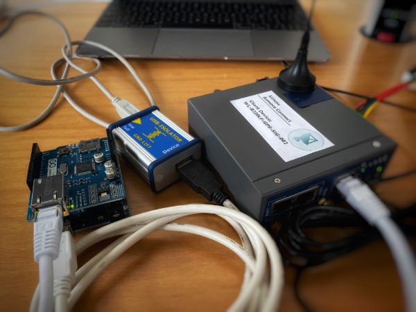
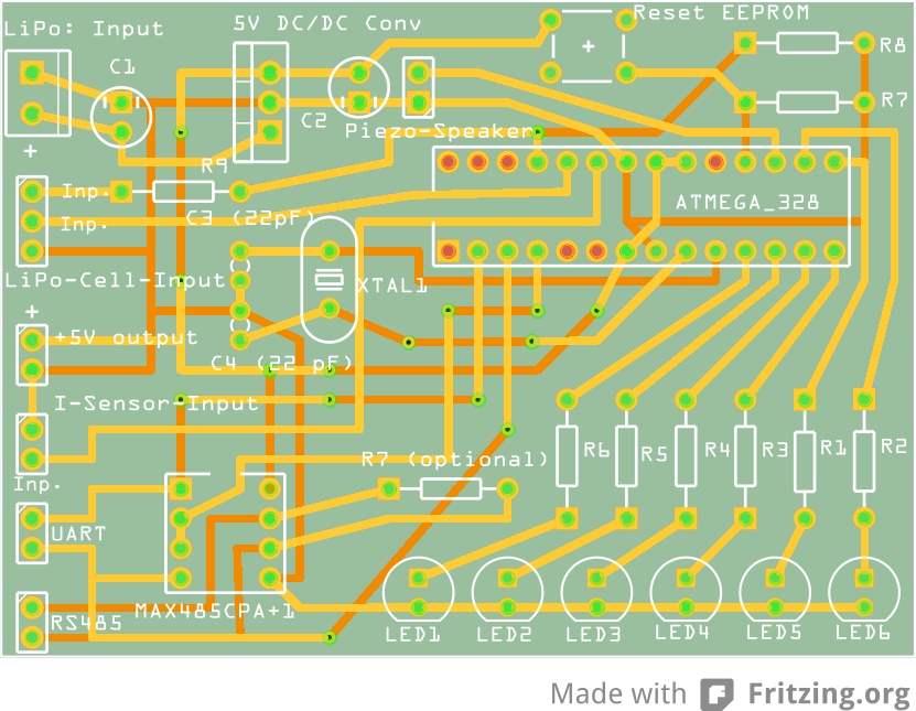
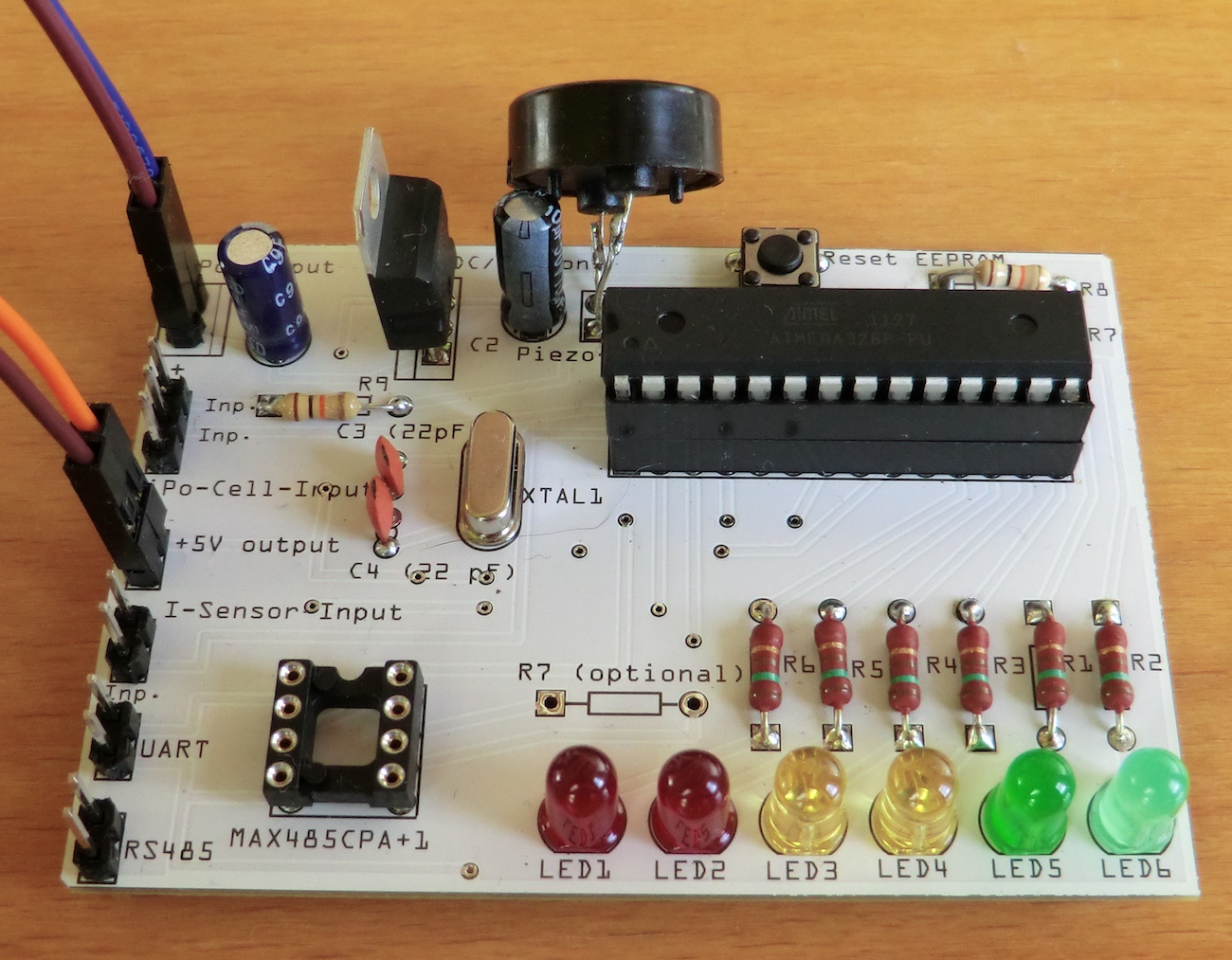
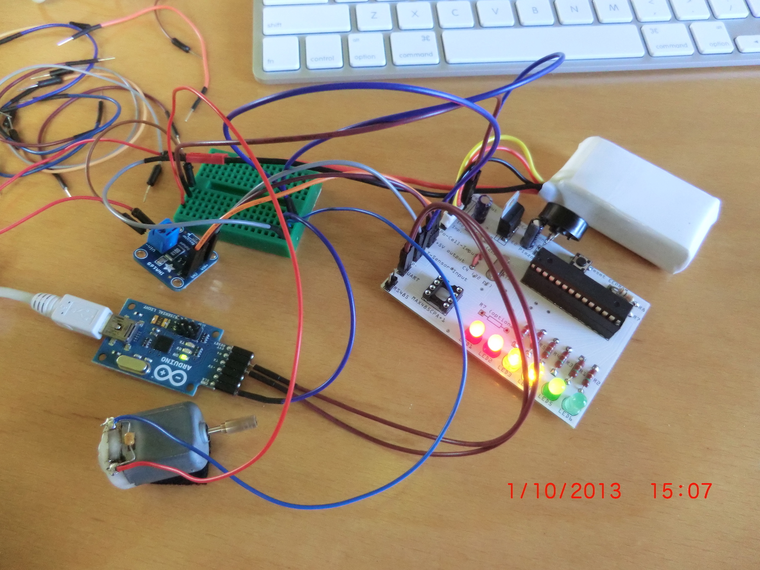
Therefore I built a LiPo monitoring board. I did the board layout by my self with Fritzing PCB Editor and the board production was done by the Fritzing Fab. Then I soldered all the needed components on the board.
The RS485 transceiver is missing on the picture below because at that time I was still testing.
Application working diagram
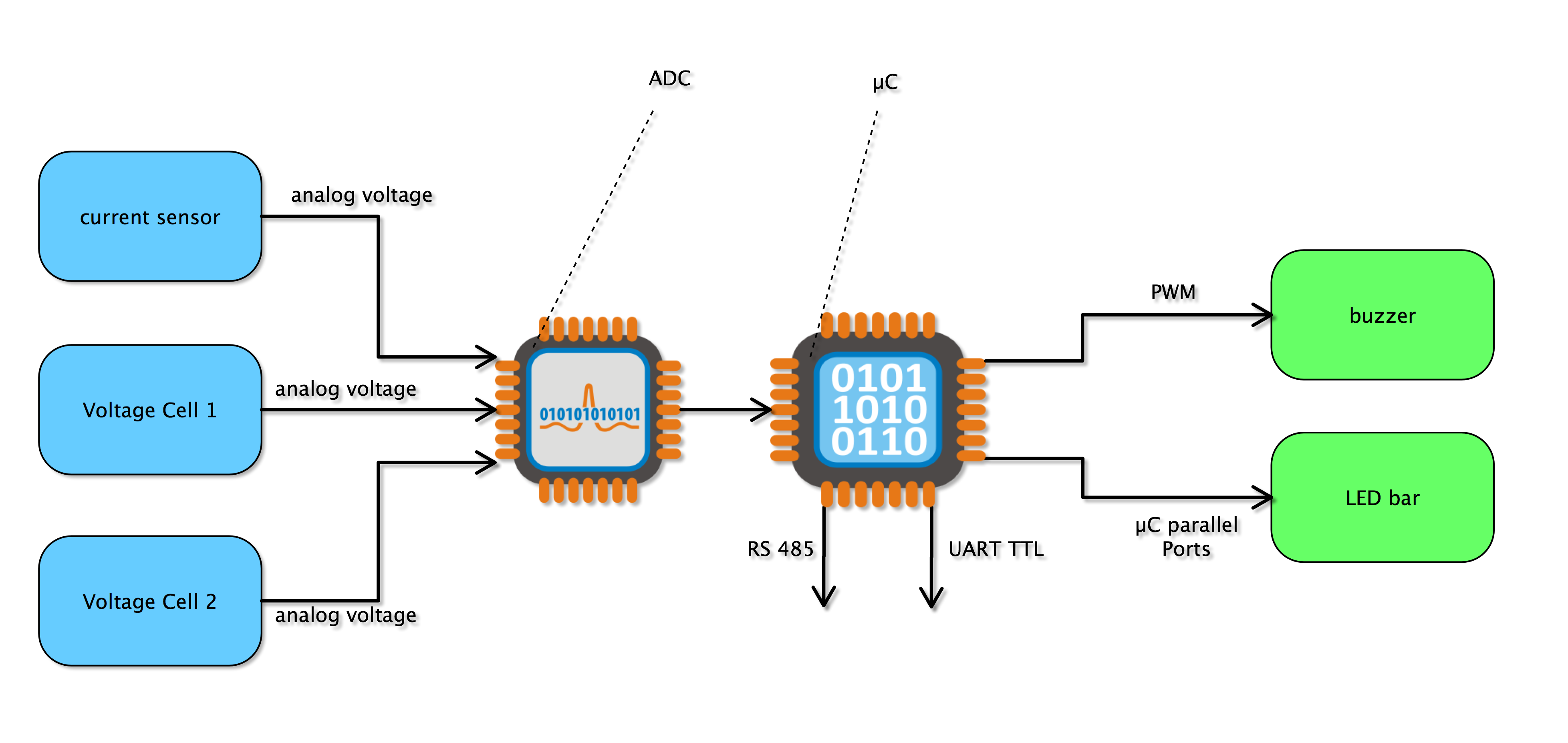
This board is able to monitor a LiPo with maximum of 2 cells. It monitors the battery the following way:
- Voltage surveillance for cell 1 and cell 2 (if voltage per cell < than 3.5 V, a warning signal is played)
- Current flow out of the battery is recorded and in case the taken capacity is greater than the batteries maximum capacity a warning signal is played
- 6 LEDs show the state of charge
- UART-TTL (RS-232) interface transmits information about cell voltage (cell 1 and cell 2), capacity taken out of battery, current and state of charge (percent) to another application
- RS-485 transceiver allows to transmit the above named parameters to another application using the RS-485 bus (data protocol UART)
For monitoring the capacity taken out of the battery a current sensor is needed (not on board). I decided not to solder a sensor to the board because depending on the application the max current is different.
The batterie's balancer connector is plugged into the "Lipo-Cell-Input", the current sensor is plugged into "I-Sensor-Input".
The current sensor I used (INA169 on a breakout board) returns a voltage between 1 and 5000 mV. 1 mV equals 1 mA.
Then I used the µC (with C++/Arduino language) to record the voltage; the current sensors output is connected to one of the ATmega’s 328 adc inputs.
The value returned by measuring one time per second (assuming that the current will not change that fast) is treated as mAs (mA*second) and is transformed into mAh by the µC firmware. Then the software totals the measured values and compares this to the batteries capacity. Is the max capacity taken out of the battery, a warning signal is going to play.
Flowchart for the µC firmware
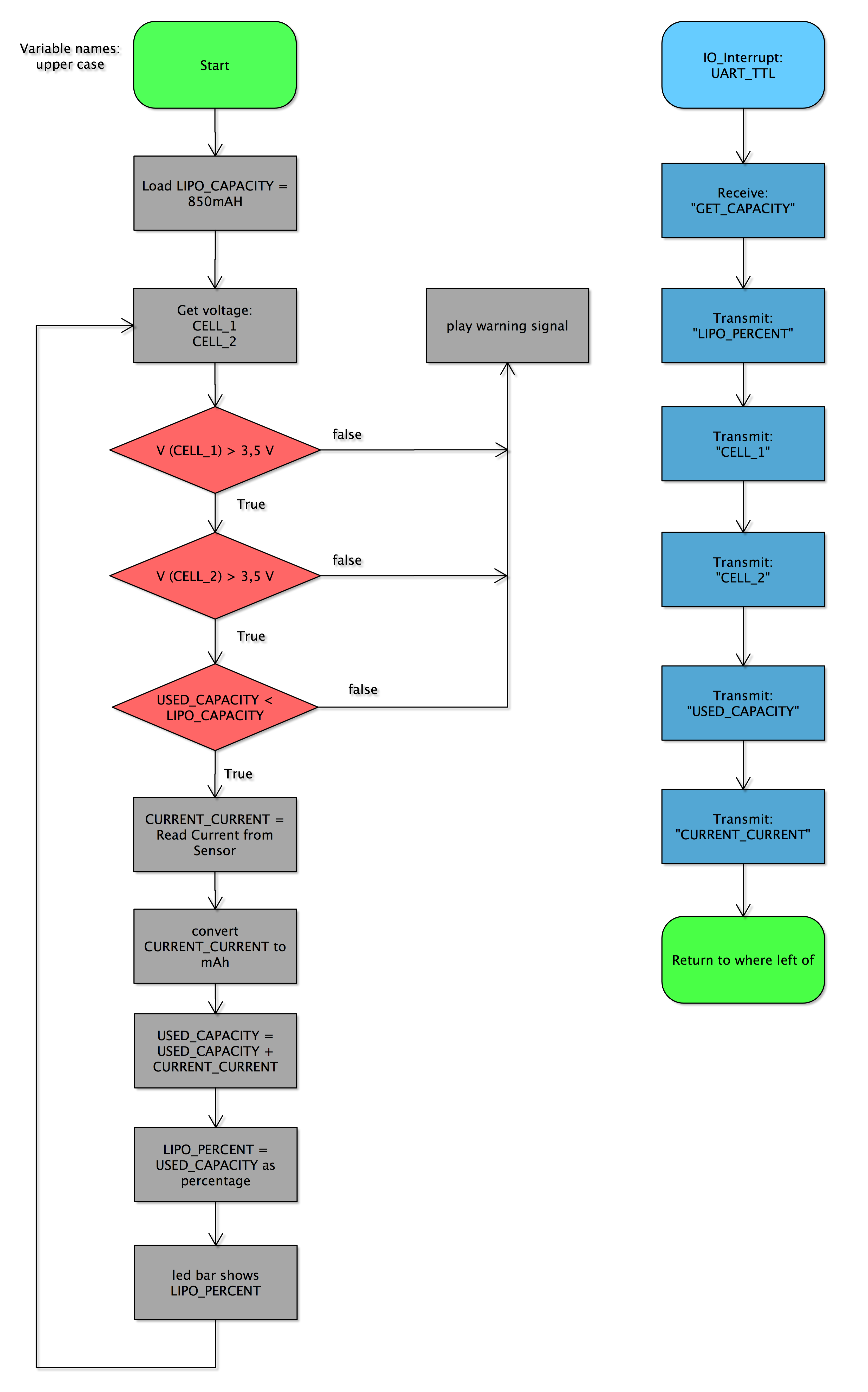
The serial port handling is not really done with an interrupt, it is done with the "serialEvent" function. This function is called every time "void loop()" is at its end and checks wether there is serial data received by the UART. If serial data is available, the function will execute the contained code and then continue with the "void loop()".
Testing and Evaluating environment
GUI for Data evaluation and visualization
Then I wrote a Python App with a tkinter GUI to display the data on my computer.
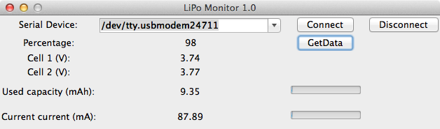
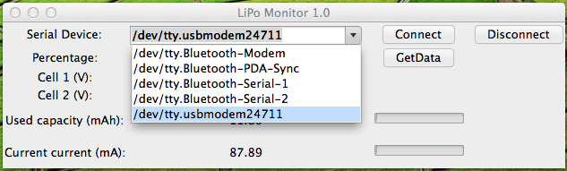
The data provided by the board is displayed via labels. The parameters "current current" and "used capacity" is additionally shown via progress bars.
By pressing the "GetData" button a separate thread is stared which communicates with the monitoring board (via UART-TTL).
The above named thread is executing an endless loop which is not able to terminate itself. I used the python module "thread" which is able to execute functions as a separate thread. By pressing the "Disconnect" button the serial interface is closed down and then the thread stops because the accessed resource is missing. Normally this would end up in an unhandled exception but I am executing the serial communication inside an "try: except:" construct which catches this error first.