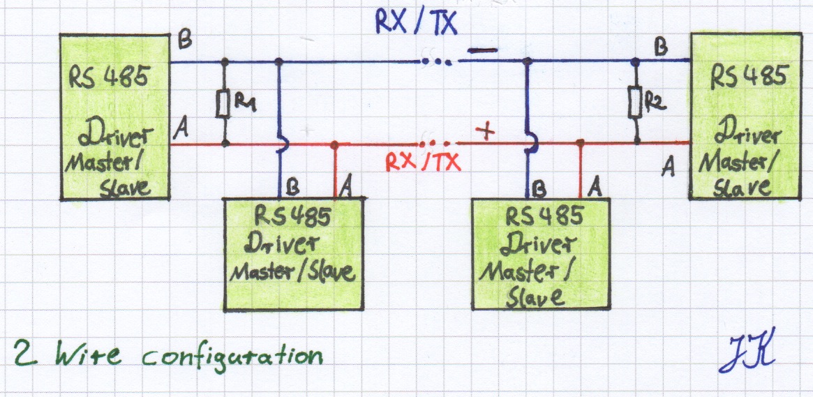
There are many reasons why you may need an RS485 bus. Imagine you have a cluster of microcontrollers and/or embedded computers far away from each other. Then an RS232 or TTL serial connection is not useable, because the cables are to long, the signal is damped and data cannot be transmitted. With a RS485 bus it is possible to use a cable length up to 1200 m (with a data transmission speed of 100 kbit/s). The RS485 bus normally uses two wires, + and -, this configuration allows to use it half-duplex (members can talk to each other but sending and receiving at the same time is not possible).
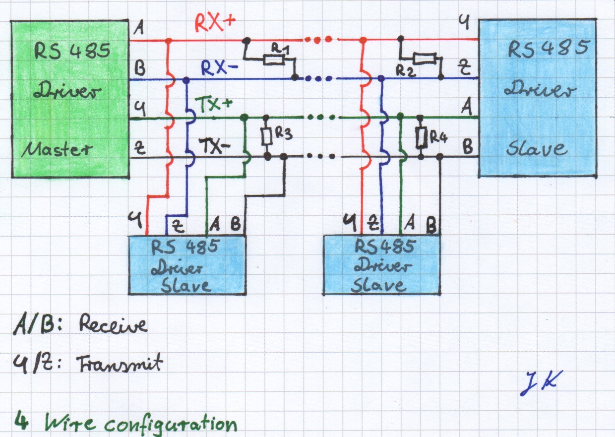
With a 4 wire configuration, the RS485 bus is able to work in full duplex mode (sending and receiving at the same time). When using this configuration you have to deal with some limitations (e.g., bus-slaves are not able to talk to each other, communication is limited to: Bus-Master -- > Bus-Slave, Bus-Slave -- > Bus-Master).
By the way, RS232 was not designed to work as a bus. Anyway, it is possible to make RS232 work as a bus connection, but this is not recommended. If it is really necessary to use RS232 as abus then the main task is to make up and implement something like an addressing scheme and protocol header.
This entry shows the easiest way how Arduinos (or other microcontrollers) can communicate via RS485.
Parts I used:
- MAX485CPA+
- Arduino Uno (2x)
- Arduino Serial to USB light
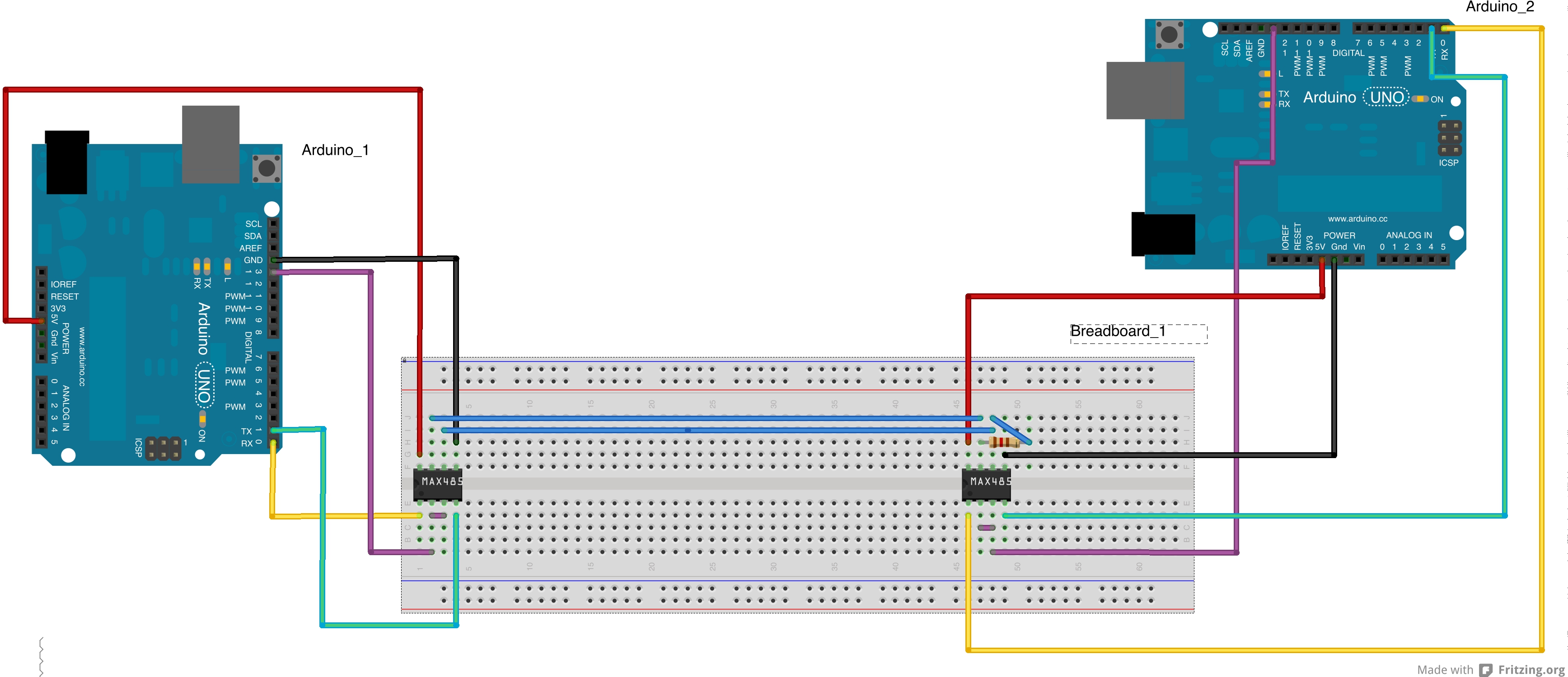
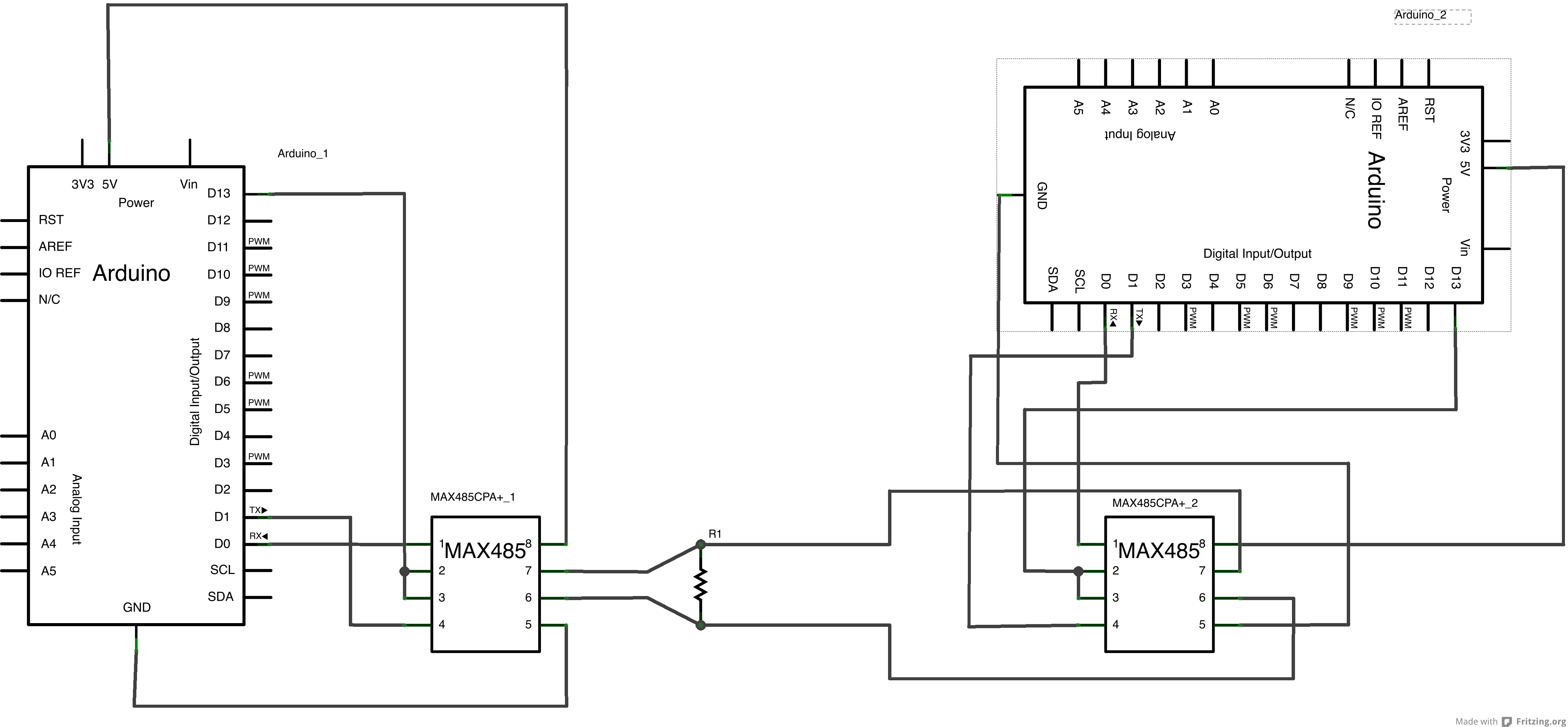
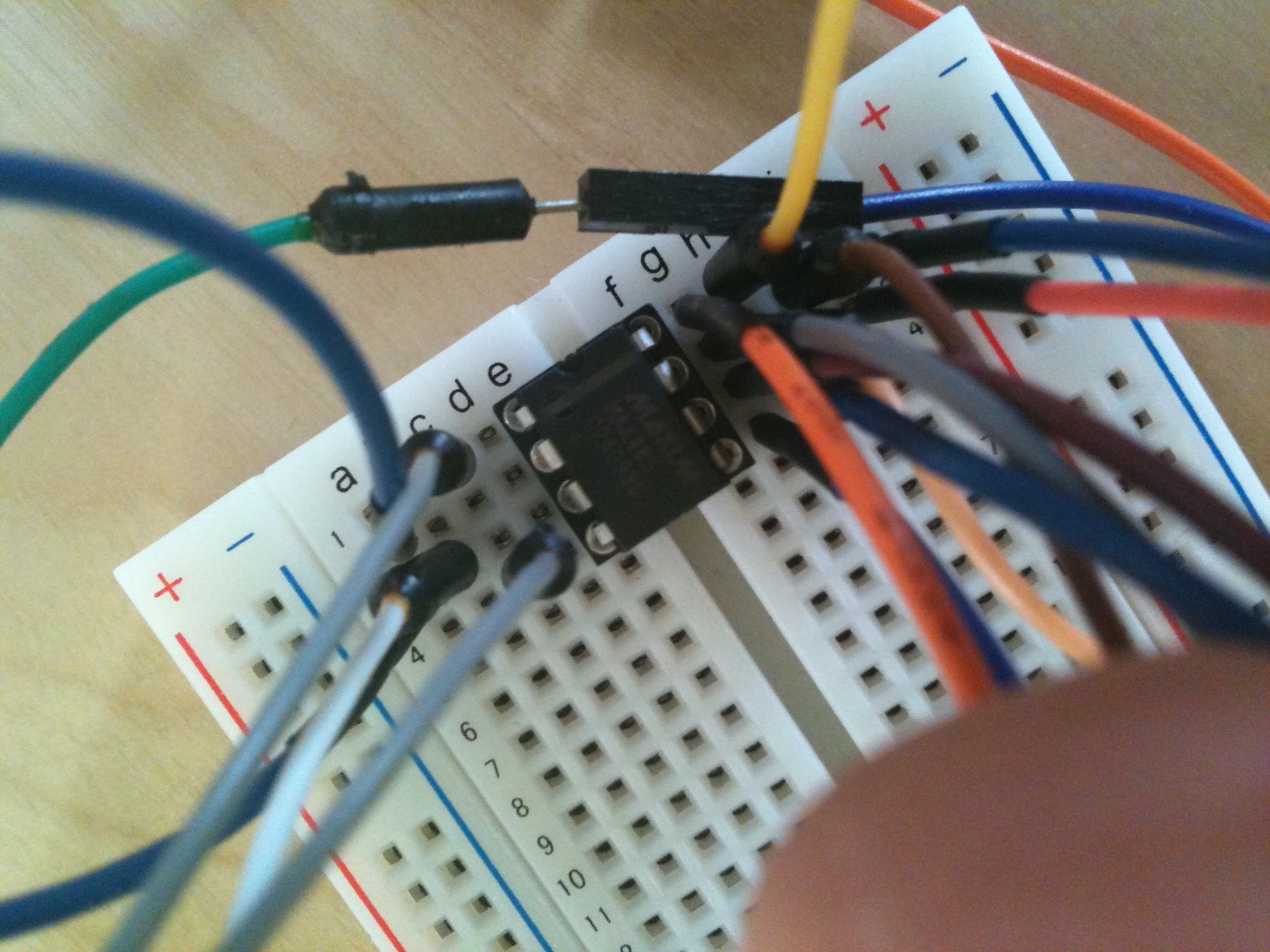
Connecting the Arduino to the MAX485 chip is easy (as you can see in the diagrams). The serial ports are connected to the max485 input and output. This is done for each master/slave.
The RS485 bus signal is between pin 6 and pin 7, there the RS485 bus allows it to connect up to 32 master/slaves.
Important for the signal transmittance are resistors at the end of the cable. In this case I used a 120 (R1) Ohm resistor between pin 6 and 7. For longer distances and more members it is recommended to put a 120 Ohm resistor between pin 6 and 7 for the first and the last bus member. No resistors for every other member.
In this case I only installed one resistor because the cable is very short (about 5"). For very short distances a resistor is normally not needed.
The sketch for the arduinos is easy!
Just write to the ttl-serial ports as usual. Of course the baud rate has to be the same on each bus member.
BUT: You may have recognized that I have connected pin 2 and 3 to Arduinos digital output on pin 13. This is necessary to tell the MAX485 chip wether it should read or write to the bus line.
While writing to the bus line, pin 2 and 3 have to be at logical HIGH, for listening to the bus line pin 2 and 3 have to be at logical LOW.
As supply voltage I used 5 V.
Not shown in the diagrams above, is the Arduino Serial to USB light converter. I just used this to grab the received signals.